
Ethernet cables play a vital role in modern networking, allowing us to connect devices like computers, switches, and routers for communication. The copper cables used in Ethernet standards are UTP cables, which stands for Unshielded Twisted Pair. This type of cabling has become a staple for Ethernet-based networks due to its reliability and cost-effectiveness.
What Is a UTP Cable?
A UTP (Unshielded Twisted Pair) cable consists of four pairs of wires, making a total of eight individual wires. These wire pairs are twisted together, and the twisting provides a clever way of reducing electromagnetic interference (EMI). By twisting the wires together, they become more resistant to external electrical noise, even though they are unshielded, which makes them vulnerable to electrical interference in some environments.
Despite the lack of shielding, the twists in the wires help minimize signal degradation, which is why UTP cables are widely used in Ethernet connections.
Ethernet Cable Categories and Pin Layouts
Ethernet cables have different standards depending on the speed and functionality they offer. For example:
- 10Base-T and 100Base-T (commonly referred to as Ethernet and Fast Ethernet) use only two pairs of wires, or four wires in total.
- 1000Base-T (Gigabit Ethernet) and 10GBase-T use all four pairs, meaning all eight wires are active.
This means that not every Ethernet standard utilizes all eight wires within a UTP cable, but they are still physically present in the cable and the RJ-45 connectors that plug into devices.
RJ-45 Connectors and Pin Mapping
The RJ-45 connector is a key component in Ethernet cabling, used to terminate the UTP cable and plug it into devices such as computers, switches, and routers. The RJ-45 connector has eight pins corresponding to the eight wires in the UTP cable. However, in Fast Ethernet (100Base-T), not all of these pins are active.
- Pins 1 and 2 are used for transmitting (TX) data.
- Pins 3 and 6 are used for receiving (RX) data.
This setup allows for Full Duplex transmission, which means data can be sent and received at the same time without causing collisions. This is because the transmit and receive pins operate on separate wire pairs.
Full Duplex and Data Transmission in 100Base-T Ethernet
In Full Duplex communication, devices can simultaneously send and receive data through their designated pins. For example:
- A PC transmits data on pins 1 and 2 and receives data on pins 3 and 6.
- A switch does the opposite: it receives data on pins 1 and 2 and transmits data on pins 3 and 6.
This design allows for seamless communication between devices, where data flows continuously in both directions without interference.
Understanding Straight-Through and Crossover Cables
There are two main types of Ethernet cables based on how the wires are arranged:
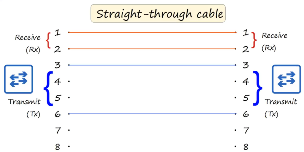
- Straight-Through Cable:
- Pin 1 on one end of the cable connects to Pin 1 on the other end, Pin 2 connects to Pin 2, and so on.
- This type of cable is used to connect devices that transmit and receive on opposite pins, such as a PC to a switch or a router to a switch.
- Crossover Cable:
- In a crossover cable, the transmit and receive pairs are reversed. For example, Pin 1 on one end connects to Pin 3 on the other, and Pin 2 connects to Pin 6.
- This cable is used when connecting similar devices like router-to-router, switch-to-switch, or PC-to-PC, which would normally transmit and receive on the same pins.
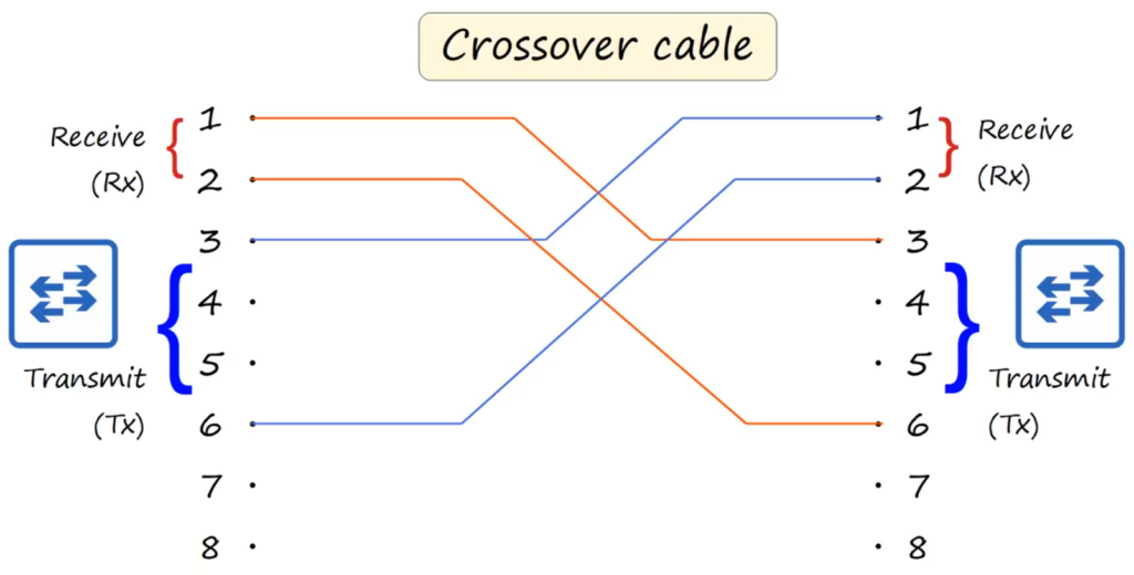
Crossover cables allow for communication between devices that transmit and receive on the same pin pairs by reversing the pairs.
Auto MDI-X: A Modern Networking Feature
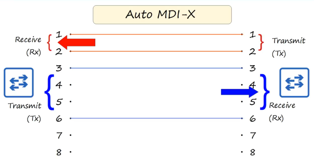
In older networks, you had to worry about using either straight-through or crossover cables depending on the devices being connected. However, modern devices often include a feature called Auto MDI-X (Medium Dependent Interface Crossover). This feature allows the device to automatically detect which pins the connected device is using for transmission and reception and adjust its pin usage accordingly.
Thanks to Auto MDI-X, you no longer need to manually determine whether to use a straight-through or crossover cable in most modern setups. Devices can automatically configure their pin settings to ensure proper communication.
Pin Configurations for Various Devices
Different networking devices, such as routers, switches, and PCs, use different pin configurations for transmitting and receiving data. Here’s a quick summary of the common pin configurations:
- PC/Router:
- Transmit: Pins 1 and 2
- Receive: Pins 3 and 6
- Switch:
- Receive: Pins 1 and 2
- Transmit: Pins 3 and 6
This difference in pin usage is what makes a straight-through cable effective when connecting a PC or router to a switch, as each device transmits and receives on opposite pins. However, when connecting similar devices, such as two routers, the pin pairs need to be crossed over using a crossover cable.
Higher Speed Ethernet: Gigabit and 10 Gigabit over Copper
As Ethernet technology has evolved, higher speeds like 1000Base-T (Gigabit Ethernet) and 10GBase-T (10 Gigabit Ethernet) have emerged, offering significantly faster data transfer than earlier standards like 10Base-T and 100Base-T. A key difference in these higher-speed standards is that they utilize all eight wires in the UTP cable, not just four like their predecessors.
In Gigabit Ethernet and 10 Gigabit Ethernet, each pair of wires is bi-directional, meaning they can simultaneously transmit and receive data. This differs from older standards like 10Base-T and 100Base-T, where wire pairs are dedicated to either transmitting or receiving. The bi-directional nature of all four wire pairs helps these standards achieve higher speeds, as data flows are more efficient and concurrent.
Wire Pairs in Gigabit and 10 Gigabit Ethernet
The wires are arranged in pairs as follows:
- Pairs 1 and 2: Traditionally used for transmit and receive in lower-speed Ethernet.
- Pairs 3 and 6: Also part of the basic transmission set.
- Pairs 4 and 5, 7 and 8: These additional pairs come into play at higher speeds, allowing Gigabit and 10GBase-T to use all available wires.
This is why 1000Base-T and 10GBase-T provide faster communication and improved bandwidth over copper UTP cables, ensuring they can handle the data rates required by modern networks.
While copper Ethernet cables are still widely used, they have some limitations over longer distances, particularly at higher speeds, which has paved the way for newer, more advanced technologies like fiber optic cables, which are even faster and more resistant to interference over long distances.
Conclusion
Understanding how UTP cables, pin configurations, and the types of Ethernet cables (straight-through and crossover) function is essential for configuring and troubleshooting wired networks. Although Auto MDI-X has simplified the process by automatically adjusting pin configurations in modern devices, the underlying concepts remain important, especially when dealing with older equipment or learning the basics of networking.
By recognizing how Full Duplex transmission, UTP cable twists, and pin mapping work together, you can better understand the flow of data in network environments and ensure successful connectivity between devices.