• 01Home
  • 02About Us
  • 03Blogs
  • 04Product Reviews
  • 05My Quizzes
  • 06Login
  • 07Signup

4 – Understanding Networking Models: OSI and TCP/IP

Search Now
  • 4 – Understanding Networking Models: OSI and TCP/IP

    In the realm of computer networking, two primary models are fundamental in structuring how devices communicate: the OSI (Open Systems Interconnection) model and the TCP/IP (Transmission Control Protocol/Internet Protocol) suite. While the TCP/IP suite is more widely recognized in everyday use, the OSI model remains a significant theoretical framework that helps in understanding the protocols and standards that govern network communications.

    What is a Networking Model?

    A networking model provides a framework for categorizing and structuring networking protocols and standards. Protocols define the rules by which devices on a network communicate. These rules dictate how data is formatted, transmitted, and received across different devices. Essentially, networking models ensure that various devices from different manufacturers can interact seamlessly without compatibility issues.

    The Importance of Networking Models

    Imagine a scenario where manufacturers like Dell and Apple each developed their own proprietary networking protocols. Dell devices would communicate effectively with one another, and the same would be true for Apple devices. However, without a standard model, a Dell PC would be unable to communicate with an Apple iMac. This lack of interoperability would pose significant challenges in today’s diverse technological landscape, especially in environments like the internet, where devices from various manufacturers need to work together.

    Both the OSI model and the TCP/IP suite help standardize network communications to overcome these issues. While the OSI model is not used in practical networking today, it provides critical insights into how network engineers conceptualize networking processes.

    The OSI Model: Layers of Networking

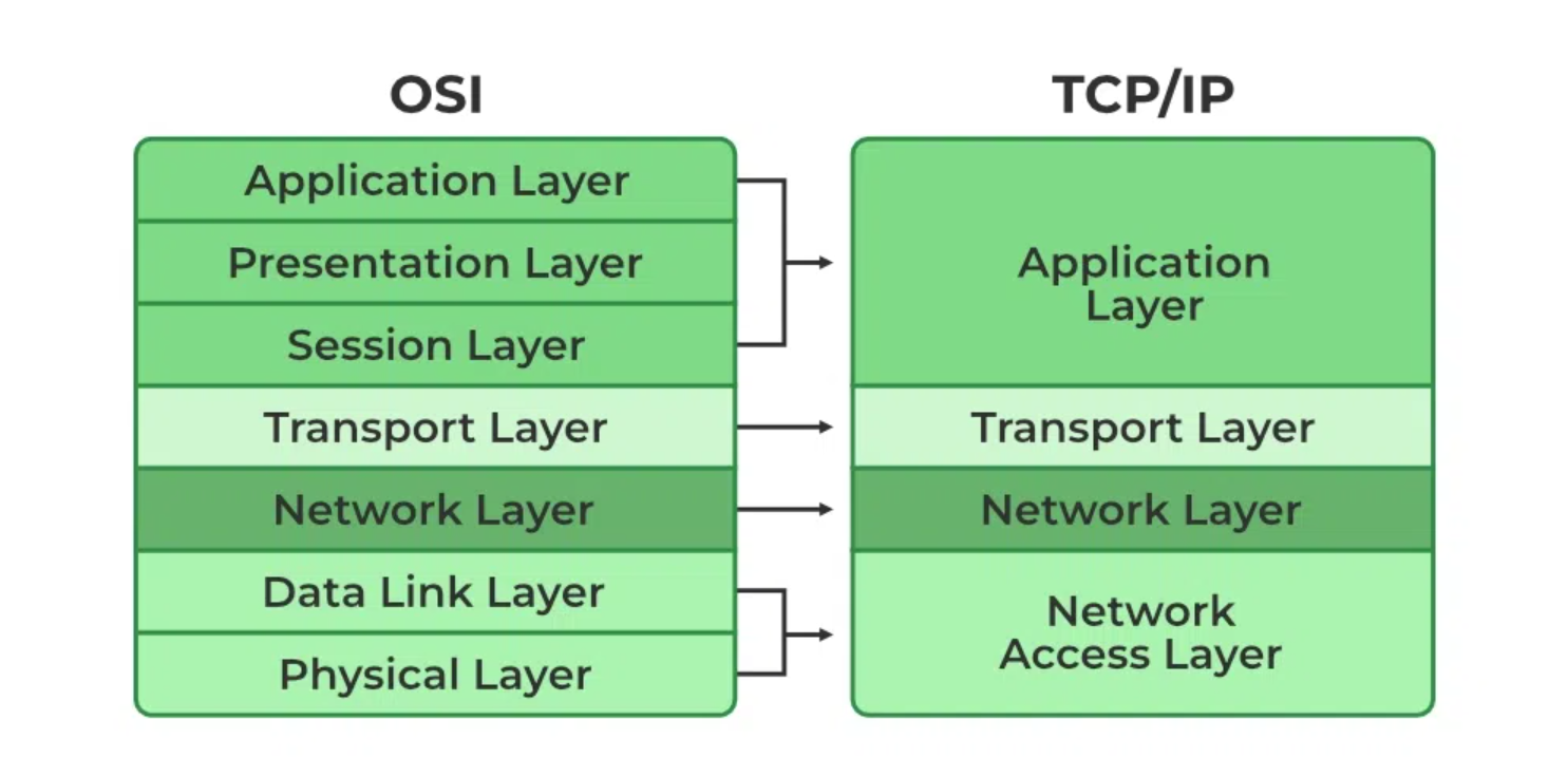
    The OSI model was developed by the International Organization for Standardization (ISO) in the late 1970s and early 1980s. It is a conceptual framework that categorizes network functions into seven distinct layers, each serving a specific role in facilitating communication between devices.

    The Seven Layers of the OSI Model

    1. Application Layer (Layer 7)
      This is the closest layer to the end user and interacts directly with software applications that facilitate communication, such as web browsers (e.g., Chrome, Firefox). Protocols like HTTP and HTTPS operate at this layer, enabling data exchange between the client and server. Key functions of the application layer include:
      • Identifying communication partners
      • Synchronizing communications
    2. Presentation Layer (Layer 6)
      The presentation layer translates data between the application layer and the network format. It ensures that data is presented in a format that the receiving application can understand. This layer is also responsible for data encryption and decryption. Its main function can be summarized as:
      • Translating data to the appropriate format.
    3. Session Layer (Layer 5)
      This layer manages sessions or dialogues between applications. It establishes, maintains, and terminates connections between devices. For instance, when multiple users access a service like YouTube simultaneously, the session layer helps manage these connections effectively.
    4. Transport Layer (Layer 4)
      The transport layer is responsible for breaking down larger messages into smaller segments for transmission. This segmentation is crucial for reliable communication, as it reduces the risk of data loss during transmission. This layer also provides end-to-end communication services and is where data is segmented and reassembled.
    5. Network Layer (Layer 3)
      The network layer provides logical addressing (IP addresses) and is responsible for routing packets of data across networks. It determines the best path for data to travel from the source to the destination, which is particularly vital in large networks like the internet. Routers operate at this layer.
    6. Data Link Layer (Layer 2)
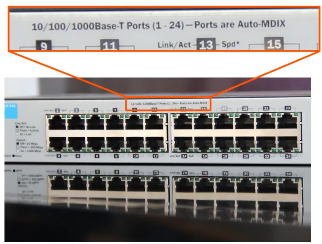
      This layer provides node-to-node connectivity and ensures that data packets are transferred reliably over the physical medium. The data link layer is responsible for framing, error detection, and addressing within a local network. Switches operate at this layer.
    7. Physical Layer (Layer 1)
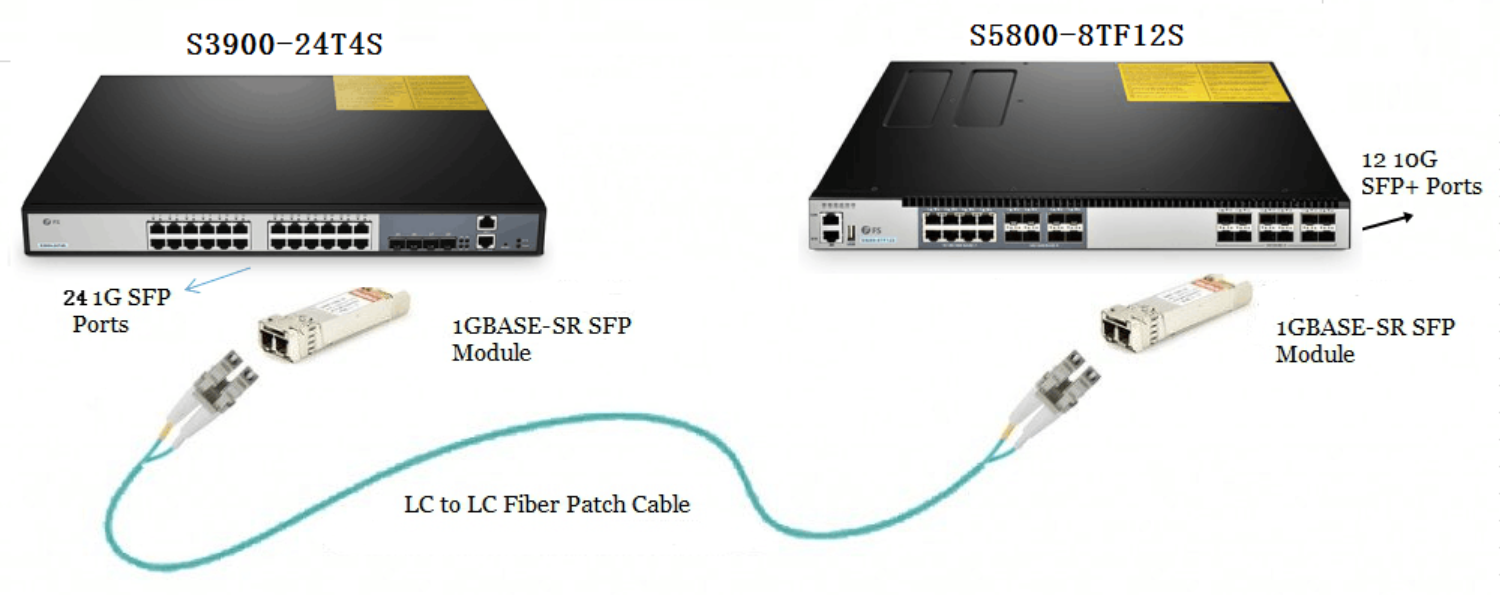
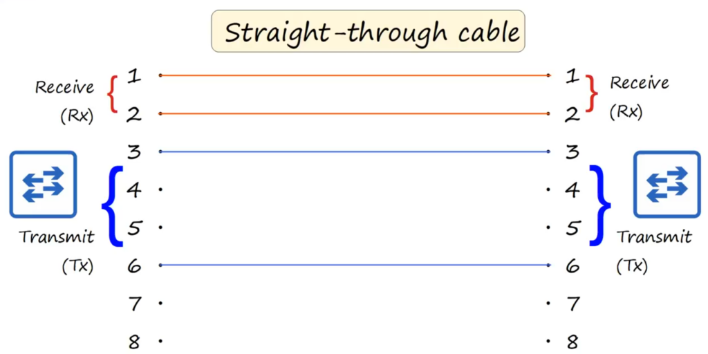
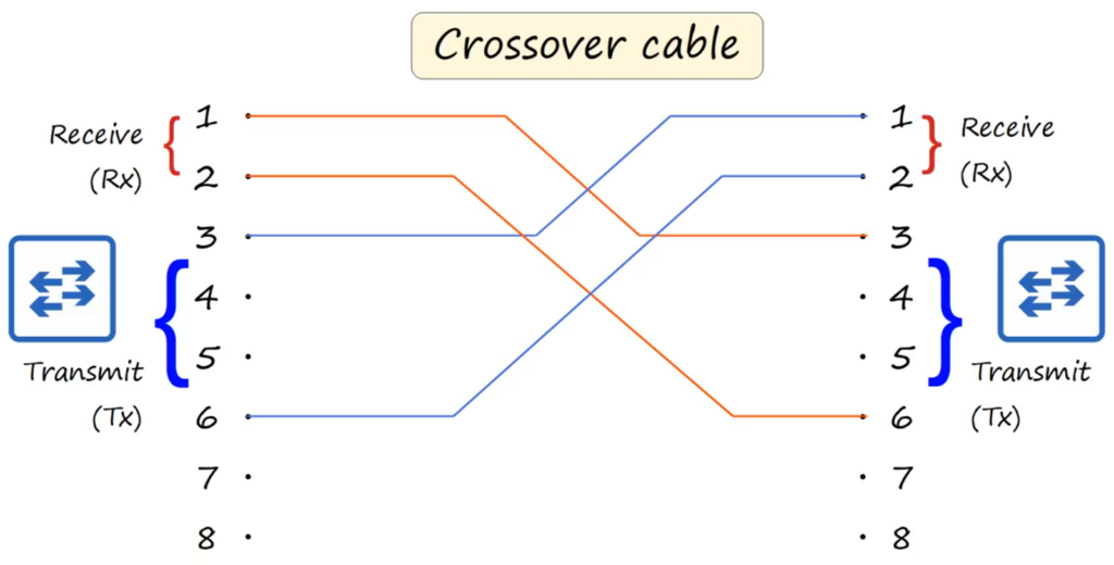
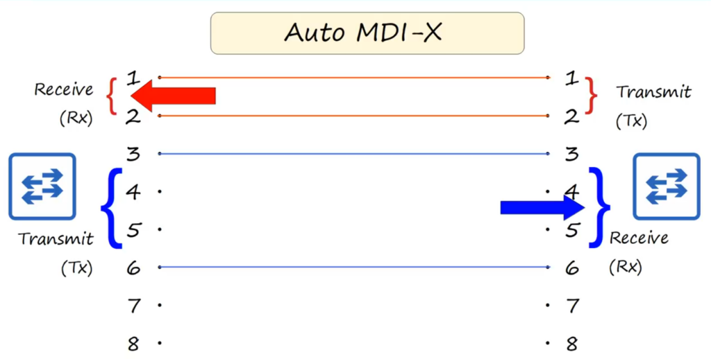
      The physical layer deals with the physical connection between devices. It defines the electrical and physical specifications of the devices, including cable types, voltage levels, and data rates. It is responsible for converting digital bits into electrical or optical signals for transmission.

    Encapsulation and Decapsulation

    A critical concept in the OSI model is encapsulation and decapsulation. When data is prepared for transmission, it moves through each layer of the OSI model, with each layer adding its own header (and possibly a trailer) to the data. This process is called encapsulation.

    • Encapsulation Process:
      • Application Layer: Data is generated and prepared.
      • Transport Layer: A layer four header is added, turning the data into a segment.
      • Network Layer: A layer three header is added, converting the segment into a packet.
      • Data Link Layer: A layer two header and trailer are added, resulting in a frame.

    Once the frame is transmitted to the destination, the reverse process, called decapsulation, occurs. Each layer removes its corresponding header (and trailer) until the original data is retrieved at the application layer of the receiving system.

    The TCP/IP Suite: A Practical Approach

    The TCP/IP suite is a practical networking model that has become the foundation of the internet. Unlike the OSI model, which is more theoretical, the TCP/IP model was developed based on real-world networking practices and has evolved to address the complexities of network communication.

    Layers of the TCP/IP Model

    The TCP/IP suite consists of four layers:

    1. Application Layer
      This layer encompasses all protocols that applications use to communicate over the network. Examples include HTTP, FTP, and SMTP.
    2. Transport Layer
      The transport layer is responsible for ensuring reliable data transfer between devices. TCP (Transmission Control Protocol) and UDP (User Datagram Protocol) are the primary protocols operating at this layer. TCP provides reliable, ordered, and error-checked delivery of a stream of data, while UDP offers a simpler, connectionless transmission model.
    3. Internet Layer
      This layer handles the addressing and routing of packets across multiple networks. The Internet Protocol (IP) is the primary protocol at this layer, responsible for delivering packets to their destination based on the IP address.
    4. Link Layer
      The link layer is responsible for the physical transmission of data over the network medium. It encompasses protocols and technologies that define how data is physically sent over the network, including Ethernet, Wi-Fi, and other technologies.

    Conclusion

    Both the OSI model and the TCP/IP suite play crucial roles in networking, with the OSI model providing a theoretical understanding of network processes and the TCP/IP suite offering practical implementations. Understanding these models is essential for anyone looking to delve deeper into the world of networking, as they form the basis for most modern network communication protocols and standards.

    As technology continues to evolve, these models will remain fundamental to the study and practice of networking, ensuring that devices from diverse manufacturers can communicate effectively in an increasingly interconnected world.

    alan

    October 5, 2024
    CCNA
    CCNA
  • 3 – Understanding Fiber Optic and Copper UTP Cabling in Networking

    In modern networking, two primary types of cables are used to connect devices: Copper Unshielded Twisted Pair (UTP) and Fiber Optic cables. Both types have their specific uses, advantages, and limitations based on distance, speed, and the type of environment. Let’s dive deeper into the structure, benefits, and differences of these two critical networking components.

    Copper UTP Cabling

    Copper UTP cables are widely used in Local Area Networks (LANs) due to their cost-effectiveness and compatibility with existing infrastructure. These cables can reliably carry data over distances of up to 100 meters, which is sufficient for most small to medium-sized networks like offices and campus environments.

    Key Characteristics of UTP Cables:

    • Cost: UTP cables are less expensive compared to fiber optic cables.
    • Construction: These cables consist of multiple pairs of copper wires twisted together to minimize electromagnetic interference (EMI). However, they can still be vulnerable to external interference and data leakage.
    • Limitations: Maximum cable length is restricted to 100 meters. Beyond this, data degradation and signal loss occur.

    A typical RJ-45 connector is used to connect UTP cables to networking devices such as switches, routers, and PCs. However, for larger and more complex networks where distance and speed are critical, copper UTP cabling may not suffice, leading to the need for more advanced cabling solutions.

    Fiber Optic Cabling: The Superior Technology

    Fiber optic cables are designed for high-performance networking, offering superior speeds and much greater distance capabilities than copper UTP. Instead of carrying electrical signals, fiber optic cables use light pulses transmitted through glass fibers, allowing data to travel much faster and further.

    Key Components of Fiber Optic Cables:

    1. Core: The inner glass fiber through which light travels.
    2. Cladding: Surrounds the core and reflects light back into it to maintain signal strength.
    3. Protective Buffer: Adds mechanical protection to the core and cladding.
    4. Outer Jacket: The external covering that shields the inner layers.

    Fiber optic cables consist of two main types: single-mode fiber (SMF) and multimode fiber (MMF).

    Single-Mode vs. Multimode Fiber

    Single-Mode Fiber (SMF):

    • Core: Narrower core diameter (typically 8-10 microns) compared to multimode fiber.
    • Light Transmission: Light travels in a single straight path through the core, which minimizes signal loss and allows for longer transmission distances.
    • Distance: SMF supports much longer distances, up to 10 kilometers or more depending on the Ethernet standard, making it ideal for long-distance communication such as data centers and metropolitan area networks.
    • Cost: More expensive than multimode fiber due to the use of laser-based transmitters.

    Multimode Fiber (MMF):

    • Core: Wider core diameter (50-62.5 microns), allowing multiple light modes to pass through the fiber.
    • Light Transmission: Light bounces at different angles within the core, leading to higher attenuation and shorter transmission distances.
    • Distance: Supports shorter distances compared to single-mode fiber, typically around 550 meters for Gigabit Ethernet.
    • Cost: Less expensive due to the use of LED-based transmitters, which are cheaper than laser-based transmitters.

    Fiber Optic Standards

    Fiber optic Ethernet standards determine the maximum distances and data transfer speeds for both multimode and single-mode fibers. Here are some common standards:

    • 1000Base-LX: Supports 1 Gbps Ethernet over both single-mode and multimode fiber. Maximum distances are up to 550 meters for multimode fiber and 5 kilometers for single-mode fiber.
    • 10GBase-SR: Designed for 10 Gbps Ethernet over multimode fiber, supporting distances up to 400 meters.
    • 10GBase-LR: Also supporting 10 Gbps, but over single-mode fiber, it can cover distances up to 10 kilometers.
    • 10GBase-ER: Extends the range further, up to 30 kilometers, also operating over single-mode fiber at 10 Gbps.

    SFP Transceivers and Fiber Connections

    Many modern network switches and routers support fiber optic connections through SFP (Small Form-factor Pluggable) transceivers. These transceivers convert the electrical signals from the device into light signals that can travel over fiber. The SFPs are typically inserted into a network device, and a fiber optic cable is connected to the transceiver for long-distance communication.

    The fiber optic cables typically use two connectors, one for transmitting and one for receiving data. This ensures that the data flow remains uninterrupted and efficient. Fiber optics, with its superior transmission distance and immunity to EMI, makes it the preferred choice for large-scale networks.

    Comparing UTP and Fiber Optic Cables

    FeatureCopper UTPFiber Optic
    CostCheaperMore expensive
    Maximum DistanceUp to 100 metersUp to 30 kilometers (single-mode fiber)
    SpeedUp to 10 GbpsUp to 100 Gbps and beyond
    EMI VulnerabilitySusceptibleImmune
    SecurityEmits signals, potential for leakageNo signal leakage, highly secure
    TransceiversRJ-45 ports (cheaper)SFP transceivers (more expensive)

    The Future of Networking

    While copper UTP cables are cost-effective and practical for short-range connections, fiber optics is the clear choice for high-speed, long-distance networking. As technology evolves, the demand for faster, more reliable communication grows, making fiber optics indispensable in data centers, enterprise networks, and internet backbones. For those building or upgrading networks, understanding the advantages and limitations of each cable type is critical for ensuring optimal performance and future-proofing infrastructure.

    Conclusion

    Fiber optic cabling is the future of networking, offering unparalleled speed, distance, and security. Although copper UTP remains useful in certain scenarios, its limitations are becoming more apparent as network demands increase. Understanding the structure, types, and standards of fiber optic cables, alongside the pros and cons of UTP cabling, equips network engineers and IT professionals to make informed decisions when designing robust and scalable networks.

    alan

    October 5, 2024
    CCNA
    CCNA
  • 2 – Understanding Ethernet UTP Cables, Pin Configurations, and Network Connectivity

    Ethernet cables play a vital role in modern networking, allowing us to connect devices like computers, switches, and routers for communication. The copper cables used in Ethernet standards are UTP cables, which stands for Unshielded Twisted Pair. This type of cabling has become a staple for Ethernet-based networks due to its reliability and cost-effectiveness.

    What Is a UTP Cable?

    A UTP (Unshielded Twisted Pair) cable consists of four pairs of wires, making a total of eight individual wires. These wire pairs are twisted together, and the twisting provides a clever way of reducing electromagnetic interference (EMI). By twisting the wires together, they become more resistant to external electrical noise, even though they are unshielded, which makes them vulnerable to electrical interference in some environments.

    Despite the lack of shielding, the twists in the wires help minimize signal degradation, which is why UTP cables are widely used in Ethernet connections.

    Ethernet Cable Categories and Pin Layouts

    Ethernet cables have different standards depending on the speed and functionality they offer. For example:

    • 10Base-T and 100Base-T (commonly referred to as Ethernet and Fast Ethernet) use only two pairs of wires, or four wires in total.
    • 1000Base-T (Gigabit Ethernet) and 10GBase-T use all four pairs, meaning all eight wires are active.

    This means that not every Ethernet standard utilizes all eight wires within a UTP cable, but they are still physically present in the cable and the RJ-45 connectors that plug into devices.

    RJ-45 Connectors and Pin Mapping

    The RJ-45 connector is a key component in Ethernet cabling, used to terminate the UTP cable and plug it into devices such as computers, switches, and routers. The RJ-45 connector has eight pins corresponding to the eight wires in the UTP cable. However, in Fast Ethernet (100Base-T), not all of these pins are active.

    • Pins 1 and 2 are used for transmitting (TX) data.
    • Pins 3 and 6 are used for receiving (RX) data.

    This setup allows for Full Duplex transmission, which means data can be sent and received at the same time without causing collisions. This is because the transmit and receive pins operate on separate wire pairs.

    Full Duplex and Data Transmission in 100Base-T Ethernet

    In Full Duplex communication, devices can simultaneously send and receive data through their designated pins. For example:

    • A PC transmits data on pins 1 and 2 and receives data on pins 3 and 6.
    • A switch does the opposite: it receives data on pins 1 and 2 and transmits data on pins 3 and 6.

    This design allows for seamless communication between devices, where data flows continuously in both directions without interference.

    Understanding Straight-Through and Crossover Cables

    There are two main types of Ethernet cables based on how the wires are arranged:

    1. Straight-Through Cable:
      • Pin 1 on one end of the cable connects to Pin 1 on the other end, Pin 2 connects to Pin 2, and so on.
      • This type of cable is used to connect devices that transmit and receive on opposite pins, such as a PC to a switch or a router to a switch.
    2. Crossover Cable:
      • In a crossover cable, the transmit and receive pairs are reversed. For example, Pin 1 on one end connects to Pin 3 on the other, and Pin 2 connects to Pin 6.
      • This cable is used when connecting similar devices like router-to-router, switch-to-switch, or PC-to-PC, which would normally transmit and receive on the same pins.

    Crossover cables allow for communication between devices that transmit and receive on the same pin pairs by reversing the pairs.

    Auto MDI-X: A Modern Networking Feature

    In older networks, you had to worry about using either straight-through or crossover cables depending on the devices being connected. However, modern devices often include a feature called Auto MDI-X (Medium Dependent Interface Crossover). This feature allows the device to automatically detect which pins the connected device is using for transmission and reception and adjust its pin usage accordingly.

    Thanks to Auto MDI-X, you no longer need to manually determine whether to use a straight-through or crossover cable in most modern setups. Devices can automatically configure their pin settings to ensure proper communication.

    Pin Configurations for Various Devices

    Different networking devices, such as routers, switches, and PCs, use different pin configurations for transmitting and receiving data. Here’s a quick summary of the common pin configurations:

    • PC/Router:
      • Transmit: Pins 1 and 2
      • Receive: Pins 3 and 6
    • Switch:
      • Receive: Pins 1 and 2
      • Transmit: Pins 3 and 6

    This difference in pin usage is what makes a straight-through cable effective when connecting a PC or router to a switch, as each device transmits and receives on opposite pins. However, when connecting similar devices, such as two routers, the pin pairs need to be crossed over using a crossover cable.

    Higher Speed Ethernet: Gigabit and 10 Gigabit over Copper

    As Ethernet technology has evolved, higher speeds like 1000Base-T (Gigabit Ethernet) and 10GBase-T (10 Gigabit Ethernet) have emerged, offering significantly faster data transfer than earlier standards like 10Base-T and 100Base-T. A key difference in these higher-speed standards is that they utilize all eight wires in the UTP cable, not just four like their predecessors.

    In Gigabit Ethernet and 10 Gigabit Ethernet, each pair of wires is bi-directional, meaning they can simultaneously transmit and receive data. This differs from older standards like 10Base-T and 100Base-T, where wire pairs are dedicated to either transmitting or receiving. The bi-directional nature of all four wire pairs helps these standards achieve higher speeds, as data flows are more efficient and concurrent.

    Wire Pairs in Gigabit and 10 Gigabit Ethernet

    The wires are arranged in pairs as follows:

    • Pairs 1 and 2: Traditionally used for transmit and receive in lower-speed Ethernet.
    • Pairs 3 and 6: Also part of the basic transmission set.
    • Pairs 4 and 5, 7 and 8: These additional pairs come into play at higher speeds, allowing Gigabit and 10GBase-T to use all available wires.

    This is why 1000Base-T and 10GBase-T provide faster communication and improved bandwidth over copper UTP cables, ensuring they can handle the data rates required by modern networks.

    While copper Ethernet cables are still widely used, they have some limitations over longer distances, particularly at higher speeds, which has paved the way for newer, more advanced technologies like fiber optic cables, which are even faster and more resistant to interference over long distances.

    Conclusion

    Understanding how UTP cables, pin configurations, and the types of Ethernet cables (straight-through and crossover) function is essential for configuring and troubleshooting wired networks. Although Auto MDI-X has simplified the process by automatically adjusting pin configurations in modern devices, the underlying concepts remain important, especially when dealing with older equipment or learning the basics of networking.

    By recognizing how Full Duplex transmission, UTP cable twists, and pin mapping work together, you can better understand the flow of data in network environments and ensure successful connectivity between devices.

    alan

    October 5, 2024
    CCNA
    CCNA
  • 1 – Understanding Network Interfaces, Ethernet Standards, and Cabling

    Introduction to Switch Interfaces

    Switches are critical components in networking, and a key feature of switches is their numerous interfaces or ports. In the image of a typical switch, you can observe multiple ports, commonly referred to by numbers such as 10/100/1000 Base-T. These labels define the speed and type of Ethernet supported by the ports.

    What Do 10/100/1000 Base-T Mean?

    • 10/100/1000 Base-T is a specification for Ethernet connections, which represents three different speeds:
      • 10 Mbps (Megabits per second)
      • 100 Mbps
      • 1,000 Mbps or 1 Gbps (Gigabit per second)

    This standard refers to Base-T, where Base indicates that the network uses baseband signaling (transmitting one signal type over the cable), and T refers to twisted-pair cabling. Twisted-pair cables are common in networks and consist of pairs of wires twisted together to reduce interference.

    Auto MDI-X

    Many switches, including those in the image, are equipped with Auto MDI-X capability. This feature automatically configures the cable settings, meaning you no longer need to worry about using specific crossover or straight-through cables for connecting devices.

    RJ-45 Connectors and Ethernet Cables

    The interfaces on most switches are RJ-45 ports. An RJ-45 (Registered Jack-45) connector is used with copper-based Ethernet cables, commonly seen in wired networks for connecting computers to switches or routers.

    The Ethernet cables themselves can vary in terms of color and design but still feature the standard RJ-45 connector. These cables transmit data using copper wiring, but other types of Ethernet cables exist, including fiber optic versions (discussed in later sections).

    Understanding Ethernet: Protocols and Standards

    Ethernet is more than just a single protocol—it’s a collection of network protocols and standards. Ethernet defines how data is transmitted over physical media like copper cables. Its protocols ensure compatibility between network devices, allowing smooth communication between computers, switches, routers, and more.

    For example, just as two people would need a common language to communicate, network devices rely on Ethernet standards to communicate efficiently, both physically (through connectors like RJ-45) and logically (through protocols like IP).

    Network Speeds and Measurements

    Network speed is commonly measured in bits per second (bps). However, it’s crucial to understand the difference between bits and bytes. Here’s a breakdown:

    • Bit: The smallest unit of data, represented as 0 or 1.
    • Byte: Eight bits form one byte.
    • Speed units:
      • 1 Kilobit (Kbps) = 1,000 bits per second
      • 1 Megabit (Mbps) = 1,000,000 bits per second
      • 1 Gigabit (Gbps) = 1,000,000,000 bits per second
      • 1 Terabit (Tbps) = 1,000,000,000,000 bits per second

    While bytes (e.g., GB) are used to measure storage, bits (e.g., Gbps) are used to measure network speed.

    Ethernet Standards and Cabling

    Ethernet standards are defined by the IEEE 802.3 working group. The most common standards include:

    • 10Base-T: 10 Mbps over twisted-pair cabling.
    • 100Base-T: 100 Mbps over twisted-pair cabling.
    • 1000Base-T: 1 Gbps over twisted-pair cabling.
    • 10GBase-T: 10 Gbps over twisted-pair cabling.

    Each of these standards specifies the speed, type of cabling, and maximum distance for reliable transmission. For example, the maximum cable length for twisted-pair Ethernet cables is typically 100 meters.

    Baseband Signaling and Twisted-Pair Cables

    • Baseband signaling refers to transmitting data over a single signal channel on the cable.
    • Twisted-pair cabling is used to reduce interference, making it ideal for Ethernet networks.

    Why Network Protocols and Standards Matter

    Just like the need for a common language between people, network protocols like Ethernet ensure that devices from different manufacturers can communicate without issues. Standards like the RJ-45 connector allow uniformity in hardware, while protocols like IP (Internet Protocol) ensure logical communication between devices across networks.

    Conclusion

    Understanding Ethernet and network interfaces is essential for anyone working in IT or preparing for certifications like CCNA. From recognizing the various Ethernet standards to understanding the role of RJ-45 connectors and twisted-pair cables, this foundational knowledge is critical for establishing reliable, efficient network connections.

    alan

    October 5, 2024
    CCNA
    CCNA
Full logo
  • About Us
  • Contact us
  • Blogs
  • Privacy policy
  • Terms

As amazon associate we earn commission from qualifying sales. Built by Alan Tech Blogs Product Reviews and Technical Quizzes. Copyright © by Alan.

Proudly Powered by WordPress